
 Another Model?
Since I started designing binaural microphones and dummy heads, one of the main issues I’ve had were related to size and portability.
The second obvious issue is that using any kind of binaural head, draws a lot of attention from all kind of human beings which ask stupid questions like what TV are you from, not realizing that they just destroyed your field recording…
It also makes react to certain animals, specially dogs, which can bark incessantly for extremely long periods of time.
Many of this experiences made me think about more camouflage for the whole rig, making it somehow smaller and more portable.
The result is the HexaRig which nicely reduces the size and makes it look more like a gadget than a humanoid.
So I have started designing this piece in a CAD program to go from ideas to prototype in a tidy way.
The main idea is basic, make the smallest possible enclosure out of wood and accommodate some tripod screws for an extension bar. Originally the idea was to use a round shape but it would make difficult to add screws for easy access to the inside, so the hexagonal shape seems better for that and it also looks way cooler like my Logo :)


I decided to use wood since I love working with it and because it has good acoustic properties, the CNC is going to be my best friend here since the CAD design make things extremely easy.
I’m using FUSION 360 at the moment because I simply love the workflow and the CAM or CNC related options, the satisfaction of how everything fits after milling is just awesome.


I used different wood colors in the CAD design to see better the different parts, but I have to admit that I quite like the look of it, so that’s is going to be the look to attempt.
Both end caps, or front/back covers will be colored using some water base dye. I love this stuff because it leaves a very homogeneous finish, is very easy to apply and clean any mess afterwards. The only problem is that it makes the wood wet and pulls the grain a lot, so needs sanding between layers slowing down the process.


After the drying of the parts, I proceed with varnish, also sanding in between layers to achieve a nice and smooth touch.
Several layers are needed to make sure it will be protected enough from some water, easier to clean and have some degree of scratch resistance.


Since I want the front to be removable but sturdy enough, I’ve decided to install the screws from the inside out so they hide once the whole enclosure is closed. To achieve the strongest connection the three screws of each side are glued with Epoxy resin.
The same is done with the tripod screws of each side, this are also critical and must be strongly installed, again some Epoxy works wonders here.
The main body and bottom cap are then glued together for a permanent connection. Alignment here is nice to get it right, then applying some weight helps make the joint flush.


Project finished! I will now mount everything in the extension bar using the tripod screws and take some pictures of the unit so you can see it properly from all angles.
I love the result of the rig and makes very easy to access inside, change ears, capsules etc. In a future post I will show the system I came up with to make the capsules easy to install or store away.
Hope you liked it and got some ideas from it!


This last christmas I decided to invest in a new spindle for my CNC so I can carry out bigger jobs, my main spindle works great but it’s not very powerful and I would rather leave it for PCB and delicate jobs, while using a more heavy-duty one for wood and rough jobs.
I decided to get a Dewalt, but after lots of checking I found out that the European prices are almost twice the american ones, making my choice extremely expensive… I only wanted a router that I can use in the CNC aswell as by hand without expending too much.
 After lots of search around ended up going for the Kress 850, which almost doubles the torque and strength of my last spindle and fits on the CNC with no modifications. However this spindle doesn’t have any router base, in fact I couldn’t find even from their brand or any third-party companies… so I made some research and decided to make one myself.
Lots of different inspiration but I found this guy, which is a genius luthier/woodworker from the north of Spain and offer lots of info, YouTube video aswell as DIY plans that you can buy for a few euros… if you like this project and this kind of stuff make sure to check his website because it´s really worth it. If you want more info click this link.
Just to say I did pay the plans for this router base as a sign of support and respect for his job, once I downloaded the files I have to say they are extremely well executed, instructions is both english and spanish, cad files, Sketchup files, images… Really worth every penny.
Even though this project is well documented, I could guess all the parts without buying any plans. In fact, even if the plans are “perfect” for my spindle, the thickness of the wood I have available was different that the one mentioned in the plans, so I had to re-do all the measurements to assure the drills and parts fit together nicely with my materials.
I decided to CNC most of my parts, but you can make all by hand using the provided templates. Make sure to be accurate with all measurements since one millimeter off may affect the final assembly.
I first cut all parts and start a dry assembly, once it fits I drill screws with countersink and apply glue.


Once I verify everything fits perfectly, I glue the parts, some like the knobs using epoxy for a strong seal. Some of the parts are the rails for the main height adjustment of the spindle, this parts must be sanded to assure a smooth movement across the hole axis before we glue anything in place.
Since this is a project that is going to be around a while, on top of all sort of surfaces I want to coat the hole thing and protect it.
In the following images I will add some captions so make sure you check the slide show of pictures to know what they are.


As you can see the system its quite simple. The rails allow the spindle to move up and down while the knobs hold it in position. When needing to adjust an exact depth you only need to insert a piece of the same thickness as the cut we want to make, between the depth adjustment system and the metal point in the base. Then adjusting the washer allows us to drop the spindle exactly the depth that we marked previously with the screw.
Checking that all fits nicely its a great surprise, and when it works its even better. The built turned up very nice and best of all works fantastically well.
The design also includes a lateral guide which allows us to make grooves parallel to an edge. Its simple but effective using some long 6mm screws, washers and a piece that acts like the guide. A clever extra here is that by turning this piece upside down and adding a pivot in the center, will make the router capable of routing,milling or cutting perfect circles.


I have to admit I really like the result of this project, because I´ve been really needing one of this for ages. If you find it interesting make sure to check the website of Paoson mentioned before, lots of inspiration there.
I hope you guys like it and find something useful around it. Cheers!
The electronics of this project was made a long time ago, after I have built several motion controllers with Arduino and stepper motors with different results. Most of them were simple one potentiometer kind of controller to allow movement in both directions, but soon this became too simple and hard replicate.
I found this little company which made some motion controllers and offered a Kit to make a small intervalometer which allows time lapses, continuous shooting and has tons of features in a very small package.
It also supports most DSLRs either using a jack trigger or Infrared LED. It has limit switches and a LTC Clock which allows to set dates and time base operations.
The problem is that it has been laying around without a case and it’s simply a mess… cables everywhere and exposed electronics… so once now that I have upgraded the slider itself, I decided to make a nice case for this little guy and finalize the project.

So the electronics of this project consist of a sandwich of three boards.
My KeyPad Shield was malfunctioning in the “select” button and also the switches are too low for the case, so I created a separate perforated PCB with 6 Omron switches of a bigger size, just connecting the old switches to the new board.
The plastic enclosure its once more made using “eco glass” which its easy to drill and cut. I did my drills and cuts using a CNC machine but it could be done by hand using a small blade. The lines which will be bent afterwards are only scored in the plastic so its easy to bend at that exact line.
Once bent, I paint the interior of the enclosure so we get a nice glossy finish looking from the exterior.


For the side panels I decided to use a normal plywood piece I had around. Using the CNC I mark a groove of 2mm in depth, inside the outer edge which will help to hold the plastic part and fit nicely.
Then I apply some dye, you can use any color you want or go for a different finish, the idea is to give it a protective coat which will help the wood if exposed in damp conditions and give it a more durable finish.


Now is when the fun starts. I decided to simply wire a new DC connector to the wooden side panel. Here we will have aswell the Jack for the DSLR trigger and a 5 Pin DIN connector (MIDI) to wire the stepper motor, which uses exactly 5 cables.
This was a decision I took so I can use the controller with other inventions I have around that use stepper motors too… like my 360º rotating table for video/photography (more info coming soon).


The electronics are screwed to the plastic enclosure, the rest of the case just “snaps” in, and stays together quite good… if anybody using this system wanted more strength you could glue the wood to the main case and leave the bottom so it can be opened… I prefer to have access and take it apart if necessary.
So I think that´s it. If any of you is interested in design or CNC files, let me know in the comments and I will prepare a small downloadable file. Hope you like it and helps somehow, cheers!
The Pl2 or “PI L Squared” it´s a tiny synth developed by the Ploytec team at Berlin. I was fascinated by their tiny synth when it came out because it had quite a distinctive 8 bit retro sound and I always have been a fan of this nostalgic sound…

For me the main interest in this device came from the fact that is tiny and can be powered from either MIDI or USB depending in their versions, which makes them super gig friendly. It also bundles with an editor for both Mac, iPad and Windows plattforms, which is where you can make all the changes and where the power of this device really resides.
It looks like a toy, but this really is no toy, but rather a complete and very well developed full on synthesizer containing to name a few of the following features:

With the editor you can access all the parameters, save presets, assign MIDI CC´s to any of the synthesizers parameters or flash the device with different alternatives firmwares which change the functionality of the device, such as the speech synthesizer which truly resembles the nostalgic Speak and Spell sound.
Anyway if you are interested and want to know more follow this link to their website page.
So it happens to exist a version of this synth in DIY factor, although their production is limited. I managed to get hold of 14 of this PCB and main ICs with the firmware on them, only had to find the rest of the parts. The idea is to make a workshop with the remaining ones and that is why I decided to make a small enclosure for it.
The functionality of the device is the same than their assembled units, just not SMT and a bit bigger but still quite small and it bundles a few extras, like MIDI and USB, 2xRCA line outputs, headphones output, volume control and an ON/OFF LED.
Here is a video (in spanish) of the workshop where I explain some of the functionality and stuff, also all the music in the background uses only the PL2 synth, make sure you check the description in the video for more info.
So for the sake of the workshop and because it really was asking for an exoskeleton, I decided to make the simplest yet sturdy and nice enclosure for this synth kit.
This system can be used with a wide range of DIY projects so I thought would be helpful to share it, or just by inspiring to some of you. The main idea is to use pieces of wood that come already in a 90º angle, to create a little wood side that also works as support of the PCB and the plastic enclosure.
Like said before the wood use is just some standard pine frames that come in 90º with a rounded edge. Here creativity its open to use all sort of variations, since there are tons to choose from in any DIY store.


Cut to size, apply some dye and wax to protect them giving them a more walnut effect and let them to cure.
Here you can use a wide variety of materials, perspex, acrylic, or like I use most of the time… some modern “eco glass” that is easy to drill, cut and its also cheap.
I start by deciding the size based in PCB measurements and score the outline using a cutter or suitable knife for it (they go for like 1€ in ebay), this allows me to easily break the plastic perfectly along the lines.


I end up with all the individual “flat” cases which still retain the protective sheet of film.
This is the only part of this project that can be harder in case you don’t have some sort of plastic bending device, there are tons of plans online about how to DIY this and its extremely cheap and easy to make. they also sell already made kits online. But most of you may have a hot air gun which can work.
Basically the lines we scored before now help to bend the plastic once heated, creating a perfect edge and also becoming quite strong when it dries.
To connect the wood parts with the enclosure and PCB I use some 2.5mm metal spacers that hold the whole structure together. Add some rubber feet and you are good to go!
The result as you can see looks great! and also feel sturdy.
Hope you like it and you find it useful!


Complete picture of my 3 pendulum Harmonograph
This is a project I wanted to make for a long time, thanks to my girlfriend who bought me a little book about Mathematics and music which I have in the car and kept reading constantly…
Only recently I have gathered enough knowledge, information and time to accomplish some complex wood work projects.
I decided to try to make my first DIY Harmonograph, a Victorian invention from 1844 that draws beautiful images based on musical tone relation such as chords, harmonics and overtones. Click here for a detailed explanation.
Following my obsession for harmonics, overtones and algorithmic music I plan to recreate old school devices as close as possible, to then create modern scaled down versions.
The first prototype seems to work quite alright, but because I wanted to make it somehow re-usable and non-permanent, there is a lot of friction and movement in the bearing system I´ve designed in order to connect the two moving arms which hold the pen.
Because of the oscillation of the pendulum and the fact that each arm pulls or pushes the other one depending on the initial force, the mechanism must allow for free movement in X and Y axis…

Some of the first harmonograph paintings.
My solution was a small “joint” consisting in two bearings at 90 degree, inserted in a small square piece of wood.
Many things learned in this process, like using rubber bands to hold stuff together, using small wooden bids as temporary bearing…
I will post images here because is a neat trick that can be used in numerous projects but all this system clearly asks for an upgrade to a more stable and accurate device.


Another crucial element of the device is the Pen Holder. The pen must be perpendicular to the painting surface and be firmly attached to one of the arms. Some pens don’t draw if the angle created by the gimbal is too steep, it’s all a try an error experience untill you find the correct weights, pen and paper so the action has as little friction as possible. Remember that most of the energy is lost while the pen is in contact with the paper.
After some tests, I decided to add some minor improvements to the arms, to allow the change of different pen holder mechanisms, bearings vs magnets, counterweights and fine adjusting the height. For that I inserted a screw at the top of each arm/pendulum so different accessories can be installed.
Magnets are great for this kind of bearing, because there is no backlash and allows free movement in all directions. However, a magnet is only holding in one side, the other one repels, so once the angle is quite drastic, the joint weakens. The second issue is that you cannot use counterweights with magnets and we will see how this is essential in future posts.
It´s also extremely difficult to glue, because they move and you must be carefull to double check they are in the correct position or else will can end up with repealing joints instead of connections. The size of this magnets must be at least 8mm in diameter or bigger, I used 5mm at first and they are not strong enough.
A trick to glue them was sticking two together so you know the direction of the magnetic poles and leaving one of them inside the wood… but is tedious and you must make one at a time, making sure the connections are correctly placed and to avoid the spheres getting out of the drills.


One of the coolest parts of this design is the use of very simple bearings using only screws that rest in a pivot hole marked on a piece of metal. The friction here can be very low and allows for fine adjusting easily.
The point in which a pendulum oscillates, is called the fulcrum.
The gimbal uses a similar system but here the main Pendulum is resting on a washer which is resting on another two pivot points at the bottom, resulting in free movement in 2 dimensions. The bottom marks in the washer are done at 90 degrees compared to the top pivot holes…. each pair of resting screws allow movement in one axis.
The top of the gimbal will accommodate a 30 by 30cm platform, made of firm and flat 6mm thick MDF. The platform was reinforced using balsa wood along the edge and supports at 45º to the main pole. The system is held in place with a screw, so it can be taken apart. In the picture below you can see magnets being use to hold in place the sheet of paper.


Like Galileo discovered a while ago, the frequency of a Pendulum comes from the length of it and not the weight.
Another interesting fact is that the frequency of the oscillation keeps constant while only amplitude decades though time due to gravity. In a pendulum we can then change the frequency by modifying the height of the weight.
A series of 12 holes are drilled in each of the pendulums, forming a complete octave with its semitones. The holes allow for a small wooden dowel to fit in acting as a limit for the weights which then will allow different frequencies to be set by each pendulum. A washer is added to even the pressure of the weights.


Considering it has been a week project, with no real expectations of a good result, I’m extremely pleased by the first results. I see a lot of room for improvement and potential upgrades that will allow more control, repetition and outstanding images so this motivates me to carry on and see what can be done.
I will post now some scanned version of the most pleasing drawings I have made while fine tuning this first prototype.


Short video of the device in use, while listening to some relaxing ambient from my Aerial EP.
Hope you guys like it!

A harmonograph is a mechanical apparatus that employs pendulums to create a geometric image. The drawings created typically are Lissajous curves, or related drawings of greater complexity. The devices, which began to appear in the mid-19th century and peaked in popularity in the 1890s, cannot be conclusively attributed to a single person, although Hugh Blackburn, a professor of mathematics at the University of Glasgow, is commonly believed to be the official inventor.[1]
A simple, so-called “lateral” harmonograph uses two pendulums to control the movement of a pen relative to a drawing surface. One pendulum moves the pen back and forth along one axis and the other pendulum moves the drawing surface back and forth along a perpendicular axis. By varying the frequency and phase of the pendulums relative to one another, different patterns are created. Even a simple harmonograph as described can create ellipses, spirals, figure eights and other Lissajous figures.
More complex harmonographs incorporate three or more pendulums or linked pendulums together (for example hanging one pendulum off another), or involve rotary motion in which one or more pendulums is mounted on gimbals to allow movement in any direction.
I started using the Arduino Pro mini long time ago. Due to it´s small size it´s ideal for finished projects so you can easily install it inside any enclosure or project. The power consumption is very low aswell and the onboard bundled options makes it for me the perfect candidate as a “brain” in many projects.

Nowadays you can find them for 2€ or less, which is incredible but truth. The new ones have even access to 8 Analog inputs increasing the standard limitation of 6 analog inputs.
Another cool feature to remember is that it´s short circuit protected, and reversed polarity too so it´s very safe to use in many scenarios… Working from anything between 3 and 12 volts DC.
There is only a small downside of using this board and its the fact that it lacks a USB connector to be programmed. You could say just use the Arduino Nano for this but truth is, the Nano goes for 9€ upwards and even if still cheap is 4 times the price of the Promini.
The good news is that there are plenty and cheap options to program it, even free if you have already an Arduino UNO lying around…
Note: you have to know which arduino pro mini you are using, either it is 5v 16mhz or 3.3v 8mhz. Use only 5 Volt and 16MHZ pro mini with the arduino uno.
If you have access already to an Arduino UNO or Mega Board, there is a very simple way to program not only a Promini but any other Arduino Board.
 In order to do this you must use a board with a Socket for the main Atmel IC so it can be removed from the PCB, some newer boards come with a SMT IC which cannot be removed from the board.
Make sure you remove the IC carefully without bending the legs. A good tip for doing so it’s using a small flat head screw driver ir order to separate one side slightly then proceed with the other side so the IC comes out easily.
Safely put the Atmel chip in a piece of antistatic foam or bag for protection and make sure you don’t lose it.
Following the wiring below you should be good to go, note how the RX pin on the Micro goes to the TX of the UNO and vice versa. Also make sure to respect polarity and voltage inputs.

This image above only shows the disconnected IC in the UNO board, the wiring differs from the micro and mini boards but they all share same concept.

Before the software can properly flash the code to the board, we must select the correct type. Since we are using a UNO but the “target” is a Promini, we will select the board in the Arduino IDE Software like if it was connected directly without the Arduino UNO in between.

A good way to test that our system is working correctly is loading the “Blink” example. In most cases the Arduino board will come preprogrammed with the Blink example, with a rate of 1000 milliseconds, I just change it to 100 milliseconds, this way as soon as the Sketch is “Flashed” to the Promini, the LED starts flashing faster. Once we are sure the “Brain bypass” is working we can proceed to upload our Sketch.
Now this is the “simple” and easy way. If you plan to use the Promini in more occasions, it makes sense to invest in a USB FTDI adapter, which is basically the USB part that is missing from a standard Arduino. This Allows us to communicate with the internal Chip using a USB connector and our computer/Arduino IDE.

This little adapters are cheap and easy to get. Just make sure you choose the correct model for your Promini. The only two options will be 3.3V 8MHZ or 5V 16MHZ.
There are versions which include a small Jumper so both 3.3V and 5V versions can be programmed.
Respect the order in the PIN connections, but most times they are already organized in a row so it matches the Arduino Pro Mini pins.
Recently I have found this version which comes in a USB form factor, it may be easier to use for certain people.

I hope this bits of info was useful and you can now freely start populating the world of Arduino ProMinis :)
In fact the technique we have discussed here, its compatible with the complete set of boards you can find around. From a UNO to another UNO, from a MEGA to a Mini, etc. Some times you are working on a project and the board stops working… you think you have Fried your Arduino, but I have noticed that many times this is only affecting the USB section of the board, while the rest of the board is still functional, this procedure is a good way to troubleshoot if the board is damaged, the Atmel chip is damaged, or simply the USB FTDI is damaged, saving you time and money.
Happy programming!
I bought my ATARI 2600 (4 Switches) in the year 2003 on an international auction for 30 dollars. At this time I was obsessed with getting all the 8 bit music systems possible, Commodores, Ataris, Nintendos, FM Chips… Without paying too much attention I bought the unit thinking that it was a NTSC system, so I bought the only game I was ever need, SYNTHCART…


This music game or software was made in PAL and NTSC, so I bought the NTSC version for proper compatibility. I tryed it and the unit was showing in a normal PAL TV but with black and white colors only… Anyway for what I used it you don´t even need a TV.
I played severall gigs back in 2006 with it, but not a big deal and then in one of those gigs the ATARI stoped working… It´s being collecting dust since then…
Now in the year 2014, 11 years after I decided to get my friend the 2600 and try to fix it, give it a clean and of course!!! it´s modding time!!! :)
The ATARI 2600 comes with an ugly oldschool RF type connector, the ones you used to have to tune, and fine tune, until you get something acceptable… The cable comes out of the unit without chance to unplug it, so the unit its far from transportable. The other problem is that this kind of connection is obsolette, and many moderns TVs or Flat screens don´t even allow it anymore, so hooking the device might be not even possible in the first place to many people.

For a long time I wanted to try and change the Video Output and use a Composite Video instead. There are numerous Kits availables online ranging from super simple to more complex ones, that even add Super Video connections.
There are many tutorials depending on what exact version you have, NTSC, PAL, 4 Switch, 6 Sitch… In my case I found the best one after searching online before buying in this link from CoolRetroProjects.
Here a Complete PDF Composite Video Tutorial for all ATARI systems.
NOTE: As suggested by the user @AnotherHowie Some of the links obove stoped working so in case you need the PDF guide use the follwing link: https://www.rbbs.be/consolekabels/Atari_2600_AV_Mod_Installation_Guide.pdf
There are basically two mods around, one very simple and the other one more complex. Both are available in ebay but they are both 20 to 30 dollars. Allthough it seems like a cheap, safe and quick option, I though to look around and match the components of the more simple one.
The component list is quite small and consist only of a few elements:
After finding many variations of the circuit online, I found this one in a image search around the internet, it´s quite clear and allows you to make it either in stripboard or normal perfboard.

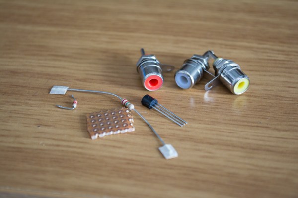
Open the ATARI unit and localize where the original RF cable plugs in to the PCB and remove the cable (image 1). It looks like a normal RCA connector (image 2).
Next to it, on the bottom right corner, there is a small metal box with a small PCB coming out of it, that is the RF Module, in order to remove it you must “cut” the 5 pins that connect to the main PCB with 90º type pins (image 3). You can just cut them and leave the module there, I decided to remove the whole RF module instead (image 4).


For picture qualitty improvement (Not necessary) remove the Transistor that is found near to the red plastic cilinder, labelled as Q201 or Q202 (image 1 and 2). Remove aswel the Resistors shown (image 3), on my case this were R209 – R222 – C205. In order to remove the metal plate and access the PCB you must “bend” the small pads. It´s possible to put it back so be carefull not to break them (image 4).


Depending on your ATARI Model, prepare the new composite video PCB and solder the cables to the right points of the circuit. Basically you must solder the new video connections to the old RF Module 5 pin connector. Please visit the PDF guides I posted in the above steps to fully understand which lines to connect depending on your model.
After that you just need to add 3 new RCA (Yellow, white and red) on the back of the unit, where we will solder or new Video and Audio outputs.
Sound is mono so just link both RCA on the connector. Test before closing the unit!
Once you know that the unit it´s working normally again, proceed to close the case and be amazed by it´s new appereance :) If it doesn´t work at the first time, don´t panic, check first other TVs around if you have the chance. I´ve noticed that different TVs reacted differently to the ATARIs signal, some of my screens wouldn´t show any image, then I changed to an old school TV we have around and it worked fantasticly.
All in all I´m quite impressed by how good this modification turned out, I spent 0€ thanks to the fact that the few components are easy to find in any old Electronic device… Never dispose Electronic rubish!! …
For a link to the original article at my site please visit this link. The post there is both in English and Spanish, plus there is an “in depth” Synthcart article, link to manuals and explanation of the Easter Egg Trick to get Visual Animationout of your Atari Synthcart!! :)
Hope you found it interesting and helpfull!!

1. INTRODUCTION
The Synthcart is a cartridge for the Atari 2600 that turns the Atari into a musical instrument. The 2600 can produce some great sounds, and the Synthcart is designed to take full advantage of all the sound features. The Atari is limited in that it cannot produce many pitches that are in tune and it only has two oscillators. However, the Synthcart is programmed with useable scales and intelligent voice management to get the most out of the Atari sound circuitry.
With basic soldering skills, it is possible to modify an Atari 2600 to get direct audio out. The Synthcart user interface is designed so that with a little practice, it can be played and programmed without the need to see the TV picture. This makes the Synth-Atari very portable since all you need is the modified Atari and an amp.
Features of the Synthcart:
2. USING THE CONTROLLERS
The Synthcart works with two Atari Keyboard Controllers, two Atari Video Touch Pad controllers, or two Atari Kid’s Controllers. I prefer the Video Touch Pads. Plug one controller in the left controller port and the other in the right controller port. The keypads are used to play notes, select beats, and to select options when the Options or Advanced Options Mode is active.
3. CONSOLE CONTROLS
The Game Reset switch activates the Options Mode and the Game Select switch activates the Advanced Options Mode. When one of these switches is pressed, the option mode is displayed for a few seconds for the user to change settings.
Combinations of the Color/B&W Switch, Left Difficulty Switch, and Right Difficulty Switch are used to select sounds.
4. PLAY MODE
The Synthcart starts up in Play Mode. In this mode you can select and play sounds and beats, and the screen will show all the current settings. To play notes, press keys on the keypads. If the Beatbox sound is selected, press a key on the right keypad to activate a beat.
To the left is a screen shot of Play Mode. You will see the current Attack/Decay/Release setting (adr), the tempo, the arpeggiator mode (arp), the arpeggiator pattern (arppatrn), the selected scale, the beatbox bank (beats), and the balance setting (bal). At the bottom of the screen, you will see which sounds are selected for the left and right keypad.
5. OPTIONS MODE
There are two options modes that allow you to change Synthcart settings. When an options mode is activated, a menu will be displayed on the screen in a grid corresponding to the keypad keys. Use the keys on either keypad to select options. Below the menu, three lines of text show the current option settings.
Options mode will close and the Synthcart will return to Play Mode after a few seconds of inactivity. If you press a keypad key twice (with the exception of the tempo adjustment) then the Synthcart will immediately return to Play Mode. Sound effects indicate when the Options Mode is entered, exited, and when options are selected. The Beatbox will continue to play in Options Mode.
Pressing the Game Reset switch will activate the standard Options Mode. The grid indicates the function of each key. For example, the upper left keypad key (1) will increase the tempo (tmp +) and the key below that (4) will decrease the tempo (tmp -). In standard options mode you can adjust the tempo, turn on the arpeggiator to 8th, 16th or 32nd notes, change the Attack/Decay/Release settings (adr) or turn on the synchronized tremolo (tre syn) or asynchronous tremolo (tre asy).
Pressing the Game Select switch will activate the Advanced Options Mode. Here, you can set the arpeggiator pattern (arp up, dwn, mix), change the scale setting (scl), set the current beat bank (bnk), and change the balance setting.
6. TEMPO
The tempo can be adjusted in the Options Mode. The following table contains the available tempo values, which have been calculated very accurately.
224.71 179.77 149.81 128.41 112.36 99.87 89.88 81.72 74.90 69.14
7. BEATBOX
The Synthcart contains 33 pre-programmed beats and patterns that can be played. When the beatbox sound is selected with the console switches, pressing a key on right keypad will start a beat playing. Pressing the lower right key (#) will stop the beatbox. To play two beats simultaneously, press two keys simultaneously. Each beat has a fill pattern that will play every four measures. There are three banks of eleven beat patterns. Select the bank in the Advanced Options Mode.
An internal metronome tracks both tempo and the measure the beat is on. If you stop a beat and then restart it while the symbol is still flashing, the beat will resume in the same measure you’re playing. This allows you to drop the beat out, keep playing, and bring the beat back in without disrupting synchronization. If you start the beat after the unit has stopped playing, the beat will start over from the beginning of its cycle. Pressing the lower right key (#) twice will instantly reset the metronome.
8. ARPEGGIATOR
The arpeggiator plays several notes in sequence. When the arpeggiator is on, holding down several keys at once on a keypad will activate it. The notes you are holding will be played repeatedly in a programmed pattern. The arpeggiator will handle up to four notes. The rate at which the notes are played depends on the arpeggiator value you select: 8th (slow), 16th (fast), 32nd (very fast). The tempo will also affect the speed. Turn on or off the arpeggiator in Options Mode.
There are three note patterns to choose from: up, down, and mix. The arpeggiator pattern may be selected in Advanced Options Mode.
Note that the Atari is not designed to read multiple keys off the keypads, so although one or two keys can be read accurately, the Atari may sometimes read keys in the wrong row when you are holding down three or more keys at once.
9. ATTACK/DECAY/RELEASE and TREMOLO
Attack, Decay, and Release determine how note volume changes when a key is pressed, held, and released. The Decay value cannot be changed, but the Attack and Release can. Set the adr in Options Mode. The following table shows the available adr settings:
_
| | Short attack and release. The note will come on immediately when a key is pressed and turn off immediately when it is released.
_
| \ Short attack, long release. The note will come on immediately, but will fade off when the key is released.
_
/ | Long attack, short release. The note will come on slowly when the key is pressed, but turn off immediately when the key is released.
_
/ \ Long attack and release. The note will come on slowly when the key is pressed and fade off slowly when it is released.
sync tremolo Special adr mode where notes will repeatedly turn on and off when played. This tremolo mode is synchronized to the tempo.
async tremolo Same as above, but this tremolo is independent of the tempo.
10. SCALES
Three scales are available: major, minor, and atonal. Unfortunately, different Atari sounds are often in different keys and have different tunings. This is a limitation of the Atari 2600 sound circuitry, but it is not difficult to compensate for. The following is a table of the sound types and what their tuning is for the major/minor scale setting.
Square Lead Bass Pitfall Saw
C -10 cents F -10 cents C# -35 cents C# -30 cents C# +10 cents
11. BALANCE
The balance may be adjusted in Advanced Options Mode. This will allow you to adjust the relative volumes of the sounds on the two keypads. Setting the balance to c (center) will make both of the sounds full volume. Setting to l (left) or r (right) will attenuate the sound on the opposite keypad.
(c) 2002 Paul Slocum
INSTRUCTIONS: synthcart_manual.pdf
PRINTABLE KEYBOARD OVERLAY: overlay.jpg
ROM: synthcart.zip
SOURCE: snthsrc.zip
For support and 8bit music discussion, check out the Synthcart Yahoo group.
MidiBud is a DIY MIDI controller with a 16×2 display, EEPROM, push-button encoder and 5 buttons. The design is based on the Mutable Instruments MIDIpal. This is a revision of the board made by the Midisizer guys, so you can order your own PCB + Atmega Pre-programmed, get the list of components and build your own!!
The MIDIpal is a smart little MIDI processor. Insert it between a MIDI keyboard (or sequencer) and a MIDI sound device to discover powerful effects and composition tools.


For this occasion I have decided to use what I have learned in the last projects, combining the idea of ETHERUS and the first CerebelUSB case. The main panels are made of acrylic, spray painted, then CNC drilled and engraved, then painted black again for a nice contrasting text.
The side panels are not just for freaking out… They are actually what keep the entire case in one piece, like a puzzle, I love this way of designing cases.
I’ve had to wire the MIDI connectors off the board so I can fit them in accordingly, they should go on the top but this makes it impossible to close it off with a case. The same is also true of the power connector, which has been reversed to the bottom of the PCB.
Due to the number of people asking me for these files for CNC, despite my comments about the difficulty. Here I leave DXF files for the wooden front, back and sides. Enjoy!

 Español