

 English
Introduccion:
Compré mi Atari 2600 (4 Palancas) en el año 2003 en una subasta internacional por 30 dólares. En aquel momento estaba obsesionado con conseguir todos los sistemas para música en 8 bits posibles, Commodores, Atari, Nintendo, Chips FM… Sin prestar demasiada atención compré la unidad pensando que era un sistema NTSC, así que compré el único juego que necesitaría, SYNTHCART…


Este juego de música o software se hizo en PAL y NTSC, así que compré la versión NTSC para la compatibilidad adecuada. He probado la unidad en un televisor PAL y se ve pero con los colores blanco y negro solamente … De todos modos para lo que pretenía usarla no se necesita un televisor.
Actué en varios conciertos en 2006 con ella, pero nada del otro mundo y luego en uno de esos conciertos la ATARI dejó de funcionar … Ha estado acumulando polvo desde entonces …
En el año 2014, 11 años después decidí coger mi amiga 2600 y tratar de arreglarla, darle una buena limpieza y, por supuesto !!! Es tiempo de cacharrear !!! :)
Atari salida de video:
La ATARI 2600 viene con un conector de tipo RF de esos retro, los que se tenían que sintonizar, ajustar y afinar, hasta que llegue algo aceptable … El cable sale de la unidad sin posibilidad de desconectarlo, por lo que la unidad es menos transportable. El otro problema es que este tipo de conexión esta obsoleta, y muchos televisores o pantallas planas modernas no te permiten usarlas, así que conectar el dispositivo podría no ser siquiera posible en primer lugar para muchas personas.

Durante mucho tiempo quise probar a cambiar la salida de vídeo y utilizar vídeo compuesto en su lugar. Hay numerosos kits disponibles en internet que van desde los muy simples hasta los más complejos, que incluso añaden conexiones de Super vídeo.
Hay muchos tutoriales en función de la versión exacta que tengas, NTSC, PAL, 4 Switch, 6 switch … En mi caso he encontrado el mejor tras buscar en la web y justo antes de comprar en este enlace de CoolRetroProjects.
PDF Composite Video Tutorial for all ATARI systems.
Mod para video compuesto:
Hay básicamente dos mods por ahí, uno muy simple y el otro más complejo. Ambos están disponibles en eBay, pero ambos valen entre 20 y 30 dólares. Aunque parece una opción barata, segura y rápida, pensé en mirar y comprar los componentes de la modificación más simple.
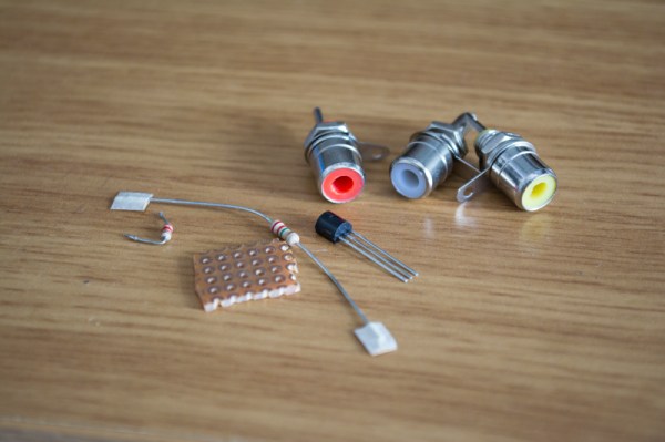
Lista de componentes:
- R 2k2
- R 3k3
- Transistor 2N3904
- 3x Conectores RCA.
Esquema:

PASO 1:
Abra la unidad ATARI y localiza donde se conecta el cable de RF original en la PCB y retire el cable (imagen 1). Se parece a un conector RCA normal (imagen 2).
Junto a ella, en la esquina inferior derecha, hay una pequeña caja de metal con un pequeño circuito que sale de ella, que es el módulo de RF, con el fin de eliminarlo debe «cortar» los 5 pines que se conectan a la tarjeta principal 90º con pasadores de tipo (imagen 3). Podrías cortar y dejar el módulo allí, pero yo decidí quitar todo el módulo de RF (imagen 4).


PASO 2:
Para mejorar la calidad de imagen (No es necesario) retira el transistor que se encuentra cerca del cilindro de plástico rojo, etiquetado como Q201 o Q202 (imagen 1 y 2). Eliminar también las resistencias mostradas (imagen 4), en mi caso estas fueron R209 – R222 – C205. Con el fin de eliminar la placa metálica y acceder al PCB debe «doblar» las pequeñas almohadillas. Es posible ponerlas de nuevo por lo que se debe tener cuidado de no romperlas (imagen 3).


PASO 3:
Dependiendo del modelo de ATARI, preparar el nuevo Circuito/PCB de video compuesto y soldar los cables a los puntos adecuados del circuito. Básicamente hay que soldar las nuevas conexiones de vídeo al viejo conector de 5 pines del Módulo RF.
Después de eso sólo tiene que añadir 3 nuevos RCA (amarillo, blanco y rojo) en la parte posterior de la unidad, donde vamos a soldar nuestras nuevas salidas de vídeo y audio.
El sonido es mono así que haga un link entre los conectores RCA Rojo y blanco. Prueba antes de cerrar la unidad!
PASO 4:
Una vez que sepas que la unidad está funcionando normalmente, procede a cerrar la carcasa y sorprendete de su nuevo estilo :)
Si no funciona a la primera vez, ¡No entres pánico!, comprueba primero otros televisores si tiene la oportunidad. He notado que diferentes televisores reaccionaron de manera diferente a la señal de la Atari, algunas de mis pantallas no muestran ninguna imagen, así que cambié a una televisión mas vieja escuela que tengo y funcionó fantásticamente.
En general estoy bastante impresionado por lo bien que esta modificación ha resultado, gasté 0 € gracias al hecho de que los pocos componentes son fáciles de encontrar en cualquier dispositivo electrónico antiguo … No descartes la basura electrónica !! …
Espero que lo encontréis interesante y útil !!

Hi interested in doing this mod. Do you have a picture of the underside of the mod board.
Hello Darren, there is an Schematic in the above post. I can´t access the inside of my Atari to make a picture, but using the schematic you should be good to go. There is plenty of info in the internet too about the matter and differences depending in the model you own.
Do you just make the traces underneath the components using solder? And the transistor is that polarised or can it go either way round..
Darren
Hello Darren. Sorry but that is a very very basic question regarding DIY and electronics.
You can use many types of already made boards, or even make your own. In this example I use what is called a PerfBoard or a Stripboard.
https://en.wikipedia.org/wiki/Perfboard
https://en.wikipedia.org/wiki/Stripboard
Yes the have Solder points behind that you can connect, or already connected in paralell lines… very easy and convenient. Go to your local electronic shop and they will know what it is, if not you can get them in eaby very cheap.
http://www.ebay.com/itm/Solderable-Perf-Board-Assortment-Kit-Copper-Pads-6-/380357917556
Hope it helps!
Hi thanks for your help and info. Ordered the board, I take it aslong as its on the traces you can space out the components more and make the board bigger.
Darren
Hi Darren, yeah with those boards you can space the componens how you prefer, to solder them you can use the Leg of the components, or else make traces where you need to. Good luck and let me know how it goes here when you finish :) !!
LOL will do, will be looking on this site for future mods and ideas haha. Great site btw! You seem to be an electronics whiz :)
lolol nice one! and thanks for your words! allthough Im not electronic whiz, more self tought and with no fear or shame to open and acomplish nerd stuff :)
Hey the mod turned out well had a good picture on my old Samsung LCD. Although, I purchased a new LG LED IPS TV yesterday and it really did not like the signal, some games it was that dark you could not see what was going on. But DVD and TV looked fantastic on it.
I did though manage to return it to Argos and swapped it for a Sony LED TV , once again I am enjoying my games, the brightness is not has good as my old TV but very playable and all interference free.
Happy Days lol. Many thanks for the help and advice!
Hey Darren! Thats great!!
Yeah many new TVs dont like the signal either, but I guess is normal and worth the risk. I´m glad it helped you and you are enjoying your games, music or whatever else! enjoy!
You are welcome Darren! Enjoy!
Hola, este tuto sive para la versión de 2 mandos
Hola Isaac, no se si me preguntas o me confirmas, en el articulo hay links donde se habla de los differentes modelos y sus distintos mods, la verdad no lo se ya q solo he hecho mod a mi Atari de 4 palancas. Suerte!
Hola inspektorgadjet me refiero a la versión Junior Model Installation – PAL, aparece, que el proceso es el mismo que el Junior Model Installation – NTSC, en el PDF de Coolretroprojects.
He seguido todos los paso y tu esquema para crear el Mod y no consigo que funcione y a lo mejor lo que voy a preguntar es una estupidez, pero una vez retiras las resistencias, el transistor y la pieza esa roja, ¿hay que puentear los puntos?, es que no hay ninguna foto en el PDF de como queda por detrás y no se si simplemente se desueldan los componentes y listo o luego hay que puentearlos, imagino que se puentean, pero no estoy seguro, si no me entiendes me refiero que entre los puntos donde había por ejemplo una resistencia, al retirarla hay que unirlos.
Hola, la info viene en los pasos 2 y 3. Es algo escueto pero basicamente, la pieza roja no hay que quitarla, se hace referencia a esta pieza porque esta cerca del transistor, en algunos mdelos este componente rojo, es el transistor que hay que quitar, pero como digo en mi modelo el transistor estaba al lado de la pieza roja, asegurate de mirar bien lo que esta escrito en tu circuito, y de quitar el componente necesario . Las resistencias mencionadas y el transistor son para mejrar imagen, pero no necesario. Las Resistencias simplemente les corte una pata y las deje levantadas pero no las quite del todo, ni hay que unir los puntos. Lo mas importante es soldar el mini circuito nuevo a los 5 puntos que se cortaron previamente del modulo RF. En el PDF de coolretro projects se eplica muy bien. Espero te sea de ayuda y si tienes problemas avisame, quizas envia una foto de tu PCB y vemos que pasa, saldudos!
Hi
Unfortunatly the 2600 Atari of mine was not on the PDF on the site
Here is the picture of it’s board:
http://up2www.com/uploads/43f7435824067-177819.jpg
http://up2www.com/uploads/43f7434320324-242567.jpg
Please highlighting the components that must be omitted and also vcc,audio in, video in.
Thank you so much
Hello Reza,
Unfortunattely that is nearly imposible for me, firstly because I cannot clearly see what is in your board. It looks to me like the components should be under the metalsquare plate at the bottom right, where that «red plastic circle is» but again, I dont know 100%.
Im afraid with those pictures I cannot be sure. Attempting to change those components without being 100% sure, may result in your ATARI 2600 never working again, so be careful.
Make sure you check online in other places, so you can find the correct model of your PCB, I think it should be aroun or one very similar to it.
Also make sure to read my complete guide in what components and traces you must find, and it may help you. Sorry I cannot offer more help.
cheers, and good luck!
Hi. Is there another place to solder the video wire on the Atari board? I screwed up the traces on my board for the video. Been a while since I soldered. If there is another place that would be great, cause right now I only have audio and no video.
Hello Jeff.
I’m not sure but it has to be one, my best bet is to use a multimeter to meassure continuity and try to find an alternative spot.
It has been a long time for me too and not really familiar with the whole thing, maybe some online forums with the original schematics or PCB could help too to follow the traces around the spot where you have affected them.
Hope you get it sorted!
Regards
Olá, quais os pontos de solda na placa para soldar os fios do circuito que ensinou a fazer?
Encontrei esse tutorial em outro local mas toda documentação que disponibilizou não está mais online.
Hola Jorge Vicente,
Siento mucho que los links no estén disponibles. Este proyecto es un proyecto antiguo y desconozco si existe la información en otros lugares.
Supongo que si compras un kit en ebay, el vendedor te pueda ayudarte con tus duda y es posible que tengan documentación al respecto.
Suerte y saludos!
Hi! I know it’s been a long time since this has been posted but I’m looking into modding some ataris. Would it be possible for you to post a more clear schematic? I’m having trouble determining where it all is on there. Maybe a basic schematic showing the schematics symbols and connections, doesn’t necessarily need to be picturized the way you had it before, I just need to see connections and I can make my own layout. Thankyou
Hello Elizabeth, sadly this is an old project I haven´t continued further, for me it worked as expected. There are kits sold on ebay maybe someone selling those kits can shine some more info and or schematics, I used the drawing here but it wasn´t made by me, I copied the diagram on perforated board and worked corretly.
Hi, I just installed the mod on my Atari 2600 clone. While double checking all voltages I realised the output voltage of the video plug was ~5 volts. After checking online, i found out it shouldn’t output more than a volt. Is this normal? It looks to me the 5v does not change value, it is directly combined with the video signal… Thanks a
Hello Peep, sadly this is an old project I haven´t continued further, for me it worked as expected. There are kits sold on ebay maybe someone selling those kits can shine some more info.
Sorry I can´t help further.