

 Español
Introduction:
I bought my ATARI 2600 (4 Switches) in the year 2003 on an international auction for 30 dollars. At this time I was obsessed with getting all the 8 bit music systems possible, Commodores, Ataris, Nintendos, FM Chips… Without paying too much attention I bought the unit thinking that it was a NTSC system, so I bought the only game I was ever need, SYNTHCART…


This music game or software was made in PAL and NTSC, so I bought the NTSC version for proper compatibility. I tryed it and the unit was showing in a normal PAL TV but with black and white colors only… Anyway for what I used it you don´t even need a TV.
I played severall gigs back in 2006 with it, but not a big deal and then in one of those gigs the ATARI stoped working… It´s being collecting dust since then…
Now in the year 2014, 11 years after I decided to get my friend the 2600 and try to fix it, give it a clean and of course!!! it´s modding time!!! :)
Atari Video Output:
The ATARI 2600 comes with an ugly oldschool RF type connector, the ones you used to have to tune, and fine tune, until you get something acceptable… The cable comes out of the unit without chance to unplug it, so the unit its far from transportable. The other problem is that this kind of connection is obsolette, and many moderns TVs or Flat screens don´t even allow it anymore, so hooking the device might be not even possible in the first place to many people.

For a long time I wanted to try and change the Video Output and use a Composite Video instead. There are numerous Kits availables online ranging from super simple to more complex ones, that even add Super Video connections.
There are many tutorials depending on what exact version you have, NTSC, PAL, 4 Switch, 6 Sitch… In my case I found the best one after searching online before buying in this link from CoolRetroProjects.
Here a Complete PDF Composite Video Tutorial for all ATARI systems.
NOTE: As suggested by the user @AnotherHowie Some of the links obove stoped working so in case you need the PDF guide use the follwing link: https://www.rbbs.be/consolekabels/Atari_2600_AV_Mod_Installation_Guide.pdf
Composite Video Mod:
There are basically two mods around, one very simple and the other one more complex. Both are available in ebay but they are both 20 to 30 dollars. Allthough it seems like a cheap, safe and quick option, I though to look around and match the components of the more simple one.
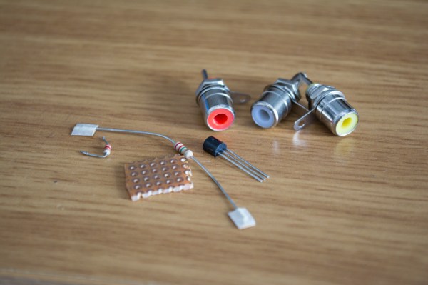
Component List and Schematic:
The component list is quite small and consist only of a few elements:
- One Resistor R 2k2
- One Resistor R 3k3
- One Transistor 2N3904
- Three RCA Connectors.
- Piece of Stripboard or perfboard.
After finding many variations of the circuit online, I found this one in a image search around the internet, it´s quite clear and allows you to make it either in stripboard or normal perfboard.
Schematic:

STEP 1:
Open the ATARI unit and localize where the original RF cable plugs in to the PCB and remove the cable (image 1). It looks like a normal RCA connector (image 2).
Next to it, on the bottom right corner, there is a small metal box with a small PCB coming out of it, that is the RF Module, in order to remove it you must “cut” the 5 pins that connect to the main PCB with 90º type pins (image 3). You can just cut them and leave the module there, I decided to remove the whole RF module instead (image 4).


STEP 2:
For picture qualitty improvement (Not necessary) remove the Transistor that is found near to the red plastic cilinder, labelled as Q201 or Q202 (image 1 and 2). Remove aswel the Resistors shown (image 3), on my case this were R209 – R222 – C205. In order to remove the metal plate and access the PCB you must “bend” the small pads. It´s possible to put it back so be carefull not to break them (image 4).


STEP 3:
Depending on your ATARI Model, prepare the new composite video PCB and solder the cables to the right points of the circuit. Basically you must solder the new video connections to the old RF Module 5 pin connector. Please visit the PDF guides I posted in the above steps to fully understand which lines to connect depending on your model.
After that you just need to add 3 new RCA (Yellow, white and red) on the back of the unit, where we will solder or new Video and Audio outputs.
Sound is mono so just link both RCA on the connector. Test before closing the unit!
STEP 4:
Once you know that the unit it´s working normally again, proceed to close the case and be amazed by it´s new appereance :) If it doesn´t work at the first time, don´t panic, check first other TVs around if you have the chance. I´ve noticed that different TVs reacted differently to the ATARIs signal, some of my screens wouldn´t show any image, then I changed to an old school TV we have around and it worked fantasticly.
All in all I´m quite impressed by how good this modification turned out, I spent 0€ thanks to the fact that the few components are easy to find in any old Electronic device… Never dispose Electronic rubish!! …
For a link to the original article at my site please visit this link. The post there is both in English and Spanish, plus there is an “in depth” Synthcart article, link to manuals and explanation of the Easter Egg Trick to get Visual Animationout of your Atari Synthcart!! :)
Hope you found it interesting and helpfull!!

Hi interested in doing this mod. Do you have a picture of the underside of the mod board.
Hello Darren, there is an Schematic in the above post. I can´t access the inside of my Atari to make a picture, but using the schematic you should be good to go. There is plenty of info in the internet too about the matter and differences depending in the model you own.
Do you just make the traces underneath the components using solder? And the transistor is that polarised or can it go either way round..
Darren
Hello Darren. Sorry but that is a very very basic question regarding DIY and electronics.
You can use many types of already made boards, or even make your own. In this example I use what is called a PerfBoard or a Stripboard.
https://en.wikipedia.org/wiki/Perfboard
https://en.wikipedia.org/wiki/Stripboard
Yes the have Solder points behind that you can connect, or already connected in paralell lines… very easy and convenient. Go to your local electronic shop and they will know what it is, if not you can get them in eaby very cheap.
http://www.ebay.com/itm/Solderable-Perf-Board-Assortment-Kit-Copper-Pads-6-/380357917556
Hope it helps!
Hi thanks for your help and info. Ordered the board, I take it aslong as its on the traces you can space out the components more and make the board bigger.
Darren
Hi Darren, yeah with those boards you can space the componens how you prefer, to solder them you can use the Leg of the components, or else make traces where you need to. Good luck and let me know how it goes here when you finish :) !!
LOL will do, will be looking on this site for future mods and ideas haha. Great site btw! You seem to be an electronics whiz :)
lolol nice one! and thanks for your words! allthough Im not electronic whiz, more self tought and with no fear or shame to open and acomplish nerd stuff :)
Hey the mod turned out well had a good picture on my old Samsung LCD. Although, I purchased a new LG LED IPS TV yesterday and it really did not like the signal, some games it was that dark you could not see what was going on. But DVD and TV looked fantastic on it.
I did though manage to return it to Argos and swapped it for a Sony LED TV , once again I am enjoying my games, the brightness is not has good as my old TV but very playable and all interference free.
Happy Days lol. Many thanks for the help and advice!
Hey Darren! Thats great!!
Yeah many new TVs dont like the signal either, but I guess is normal and worth the risk. I´m glad it helped you and you are enjoying your games, music or whatever else! enjoy!
You are welcome Darren! Enjoy!
Hola, este tuto sive para la versión de 2 mandos
Hola Isaac, no se si me preguntas o me confirmas, en el articulo hay links donde se habla de los differentes modelos y sus distintos mods, la verdad no lo se ya q solo he hecho mod a mi Atari de 4 palancas. Suerte!
Hola inspektorgadjet me refiero a la versión Junior Model Installation – PAL, aparece, que el proceso es el mismo que el Junior Model Installation – NTSC, en el PDF de Coolretroprojects.
He seguido todos los paso y tu esquema para crear el Mod y no consigo que funcione y a lo mejor lo que voy a preguntar es una estupidez, pero una vez retiras las resistencias, el transistor y la pieza esa roja, ¿hay que puentear los puntos?, es que no hay ninguna foto en el PDF de como queda por detrás y no se si simplemente se desueldan los componentes y listo o luego hay que puentearlos, imagino que se puentean, pero no estoy seguro, si no me entiendes me refiero que entre los puntos donde había por ejemplo una resistencia, al retirarla hay que unirlos.
Hola, la info viene en los pasos 2 y 3. Es algo escueto pero basicamente, la pieza roja no hay que quitarla, se hace referencia a esta pieza porque esta cerca del transistor, en algunos mdelos este componente rojo, es el transistor que hay que quitar, pero como digo en mi modelo el transistor estaba al lado de la pieza roja, asegurate de mirar bien lo que esta escrito en tu circuito, y de quitar el componente necesario . Las resistencias mencionadas y el transistor son para mejrar imagen, pero no necesario. Las Resistencias simplemente les corte una pata y las deje levantadas pero no las quite del todo, ni hay que unir los puntos. Lo mas importante es soldar el mini circuito nuevo a los 5 puntos que se cortaron previamente del modulo RF. En el PDF de coolretro projects se eplica muy bien. Espero te sea de ayuda y si tienes problemas avisame, quizas envia una foto de tu PCB y vemos que pasa, saldudos!
Hi
Unfortunatly the 2600 Atari of mine was not on the PDF on the site
Here is the picture of it’s board:
http://up2www.com/uploads/43f7435824067-177819.jpg
http://up2www.com/uploads/43f7434320324-242567.jpg
Please highlighting the components that must be omitted and also vcc,audio in, video in.
Thank you so much
Hello Reza,
Unfortunattely that is nearly imposible for me, firstly because I cannot clearly see what is in your board. It looks to me like the components should be under the metalsquare plate at the bottom right, where that “red plastic circle is” but again, I dont know 100%.
Im afraid with those pictures I cannot be sure. Attempting to change those components without being 100% sure, may result in your ATARI 2600 never working again, so be careful.
Make sure you check online in other places, so you can find the correct model of your PCB, I think it should be aroun or one very similar to it.
Also make sure to read my complete guide in what components and traces you must find, and it may help you. Sorry I cannot offer more help.
cheers, and good luck!
Hi. Is there another place to solder the video wire on the Atari board? I screwed up the traces on my board for the video. Been a while since I soldered. If there is another place that would be great, cause right now I only have audio and no video.
Hello Jeff.
I’m not sure but it has to be one, my best bet is to use a multimeter to meassure continuity and try to find an alternative spot.
It has been a long time for me too and not really familiar with the whole thing, maybe some online forums with the original schematics or PCB could help too to follow the traces around the spot where you have affected them.
Hope you get it sorted!
Regards
Olá, quais os pontos de solda na placa para soldar os fios do circuito que ensinou a fazer?
Encontrei esse tutorial em outro local mas toda documentação que disponibilizou não está mais online.
Hola Jorge Vicente,
Siento mucho que los links no estén disponibles. Este proyecto es un proyecto antiguo y desconozco si existe la información en otros lugares.
Supongo que si compras un kit en ebay, el vendedor te pueda ayudarte con tus duda y es posible que tengan documentación al respecto.
Suerte y saludos!
Hi! I know it’s been a long time since this has been posted but I’m looking into modding some ataris. Would it be possible for you to post a more clear schematic? I’m having trouble determining where it all is on there. Maybe a basic schematic showing the schematics symbols and connections, doesn’t necessarily need to be picturized the way you had it before, I just need to see connections and I can make my own layout. Thankyou
Hello Elizabeth, sadly this is an old project I haven´t continued further, for me it worked as expected. There are kits sold on ebay maybe someone selling those kits can shine some more info and or schematics, I used the drawing here but it wasn´t made by me, I copied the diagram on perforated board and worked corretly.
Hi, I just installed the mod on my Atari 2600 clone. While double checking all voltages I realised the output voltage of the video plug was ~5 volts. After checking online, i found out it shouldn’t output more than a volt. Is this normal? It looks to me the 5v does not change value, it is directly combined with the video signal… Thanks a
Hello Peep, sadly this is an old project I haven´t continued further, for me it worked as expected. There are kits sold on ebay maybe someone selling those kits can shine some more info.
Sorry I can´t help further.